Transport infrastructure / roads

Project

Construction of the Section “Bralos – Amfissa” of “E65 Lamia-Itea-Antirrio Motorway”, Greece


Location: Cetntral Greece
Client: AVAX S.A.
Date: 2023-2025
Construction costs: approx. € 285.5 million
Technical Details

The roadway corridor connecting Bralos to Amfissa constitutes a critical infrastructure intervention with pronounced socio-economic impact for Central and Northern Greece. The project, with an overall length of 24 kilometers and an estimated budget of €285.5 million, is being developed in alignment with state-of-the-art environmental specifications and engineering standards. It is strategically positioned to enhance interregional connectivity between Central and Northern Greece and the western part of the country.

The scope of works includes the construction of two tunnels, measuring 2.2 km and 2.5 km respectively, at-grade junctions, seven bridge structures, and a network of secondary access roads to ensure seamless integration with the broader road network. This comprehensive design aims to significantly improve travel efficiency and safety, while facilitating more reliable freight and passenger transport across the region.

Tunnel 2 - Τunnel Face Support
Earthworks
Bridge 1 - Pier Casting
Detailed Scope of Services
Roadway Design:

Final Roadway Design for the main motorway and side road network:

  • Subsection A: 7.3 km from Ch. 0+000 to 7+300.
  • Subsection B: 16.7 km from Ch. 14+000 to 30+700

Dsign speed of 80 km/h has been adopted. The cross-section provides a carriageway width of 14.0 meters, comprising one traffic lane per direction, each 3.75m wide. Additionally, part of the shoulders has been asphalted to form a 1.50m-wide multifunctional lane in each direction. These lanes are intended to accommodate high percentages of heavy vehicle traffic, offering operational flexibility and improved traffic flow under such conditions.

Final Roadway Design for At-Grade Intechanges

  • Final Design of I.K.1A and I.K.1B (Bralos – Palaiochori), I.K.2 (Bralos Railway Station), I.K.3 (Gravia), and I.K.6 (Viniani).

Final Design of Road Signage and Safety Installations (RSS) for all at-grade interchanges and along the main motorway and side road network in both subsections

Tunnel Engineering. Final Design for Excavation and Temporary Support, and Structural Design of Permanent Lining
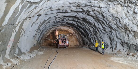
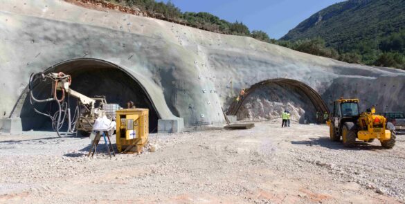
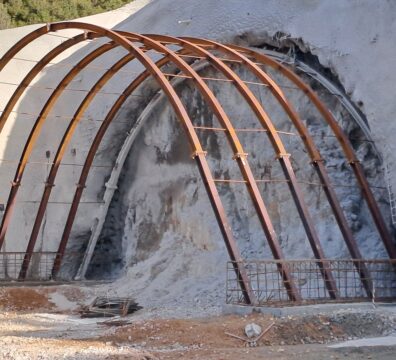
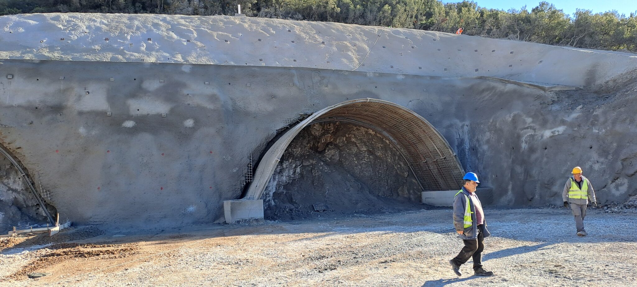
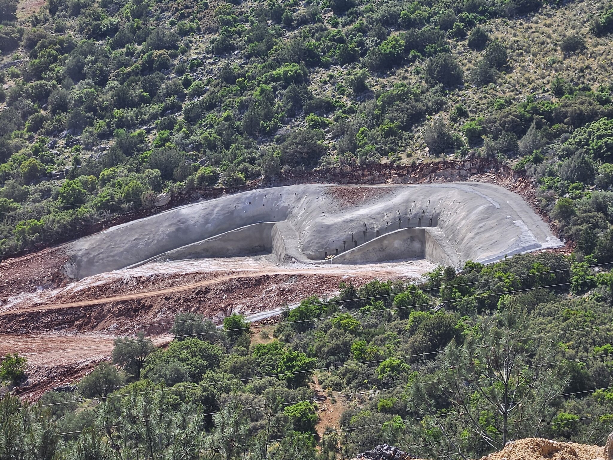
  • Tunnel 1: Ch. 16+542 – 18+752 (4300 m underground, 92 m Cut & Cover)

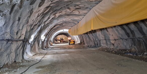
Tunnel 1 comprises the construction of twin tunnels (2164m+2136m), each serving unidirectional traffic. It includes fourpedestrian cross-passages (emergency escape tunnels) and one vehicular cross-passage at the location of emergency lay-by.

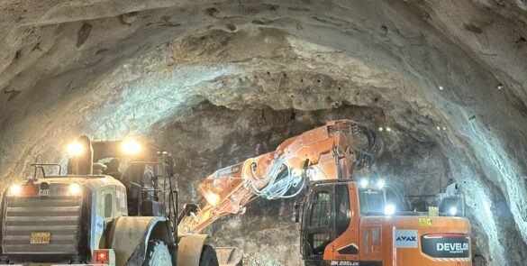
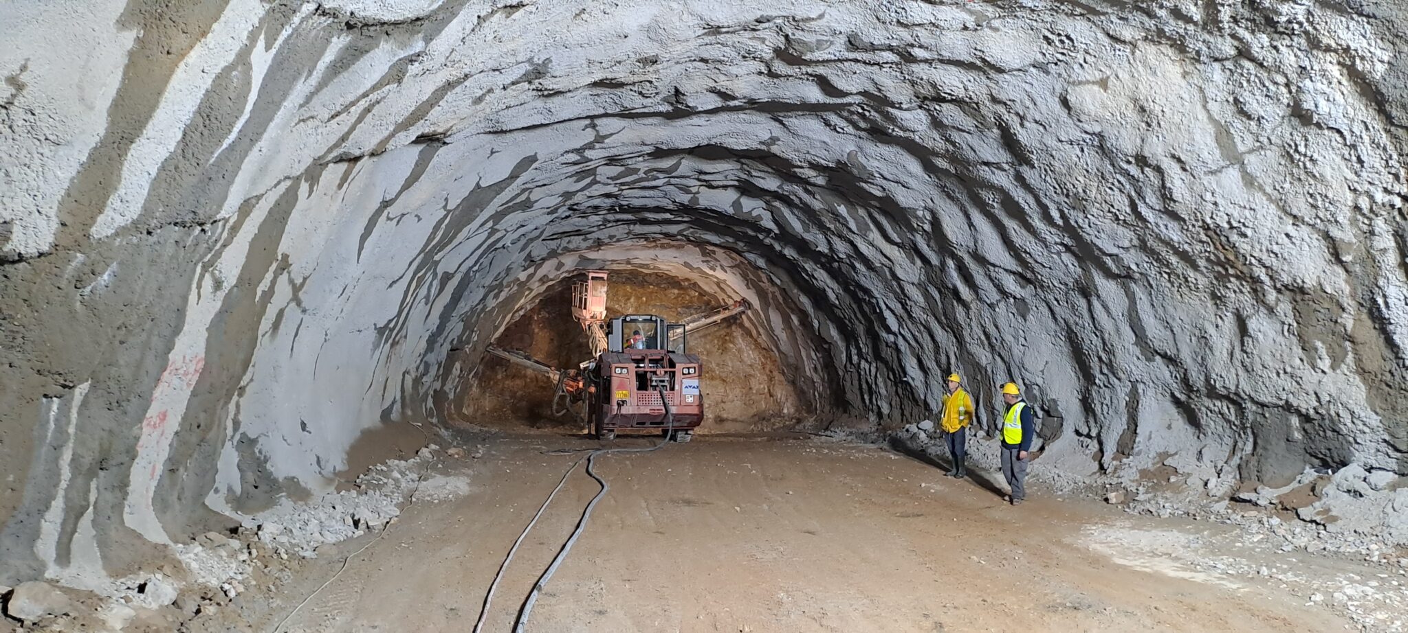
The tunnel is expected to be excavated through Upper Cretaceous limestones that are thick-bedded and intensely karstified, often containing clay-filled voids, Pelagic limestones – medium-bedded, also karstified with similar void characteristics, Marly shale phase of massive structure without distinct bedding and Flysch that is stratified formation consisting of alternating marl and sandstone layers. These formations are expected to present variable geotechnical behavior, requiring tailored excavation and support strategies throughout the tunnel alignment.

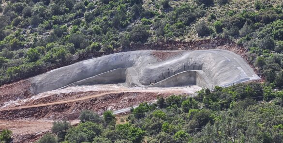
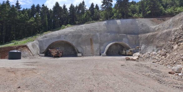
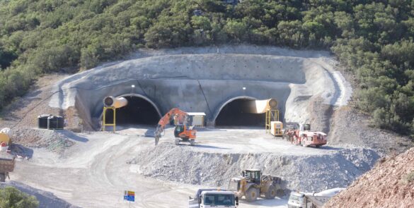
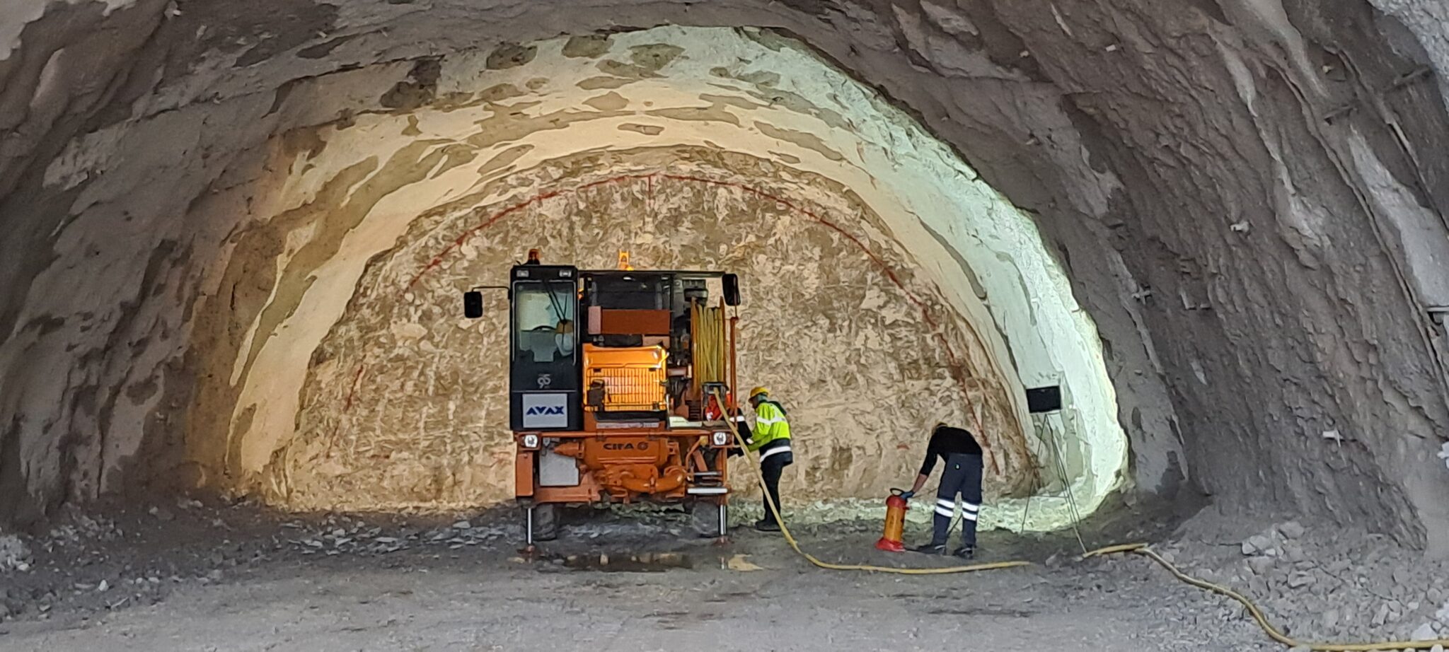
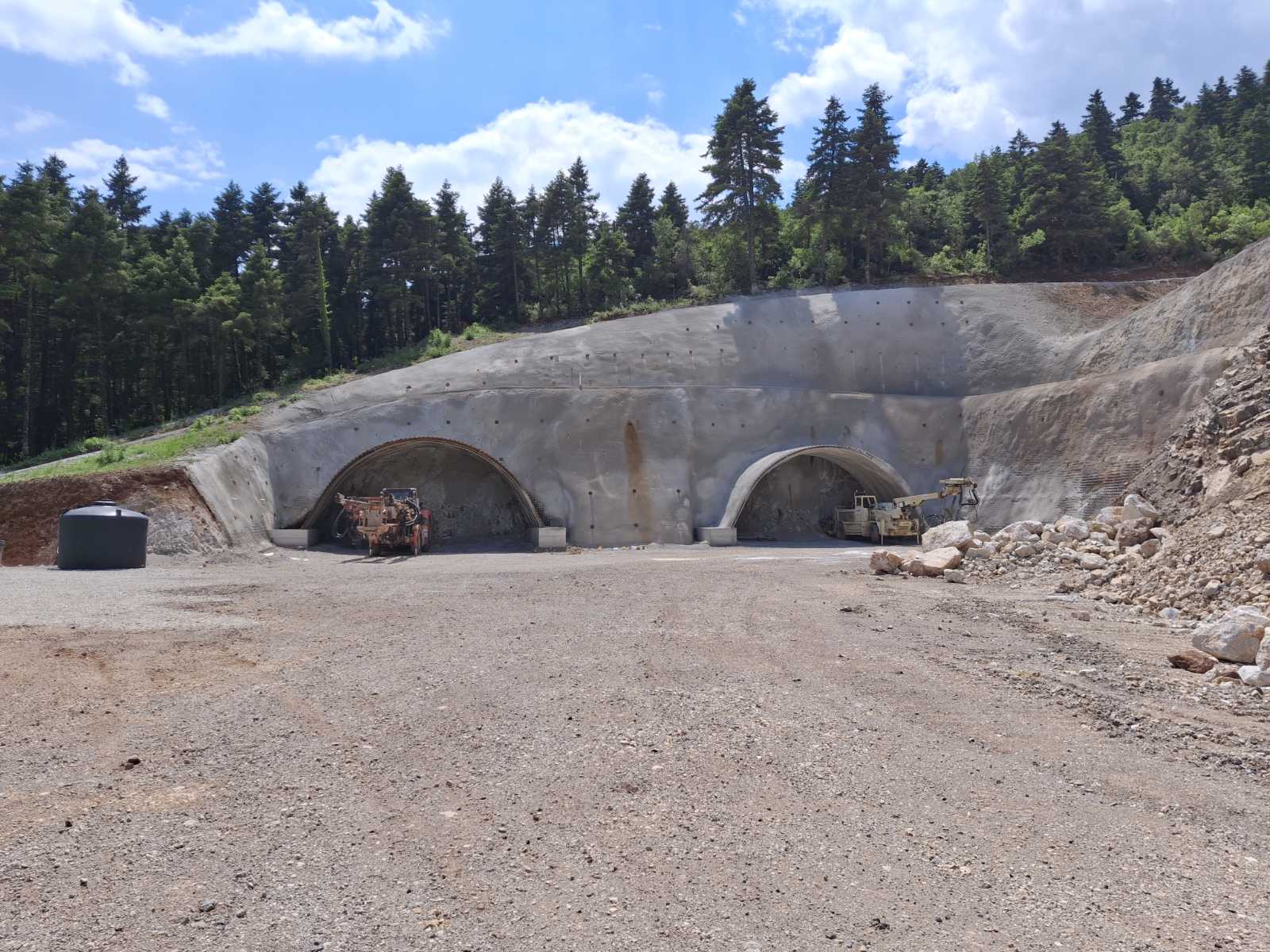
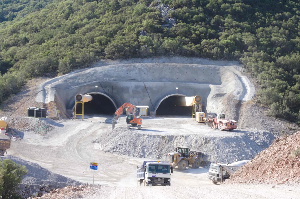
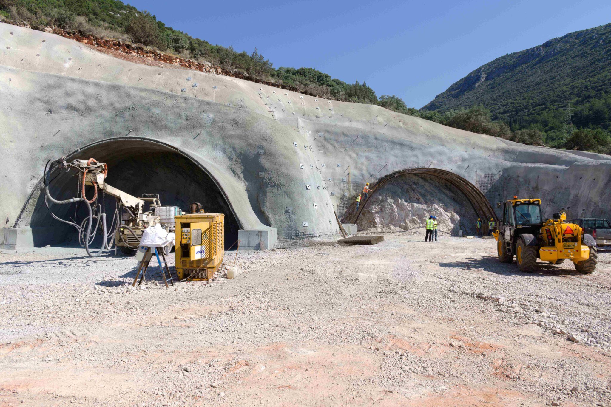
  • Tunnel 2: Ch. 23+612 – 26+105 (4890 m underground, 75 m Cut & Cover)

Tunnel 2 comprises the construction of twin tunnels (2449m+2441m), each serving unidirectional traffic. It includes three pedestrian cross-passages (emergency escape tunnels) and two vehicular cross-passages at the locations of emergency lay-bys. 

The tunnel is expected to be excavated through Upper Cretaceous limestones and intermediate limestones, both of which are thick-bedded and exhibit intense karstification, with frequent clay-filled voids. These geological conditions are anticipated to pose significant geotechnical challenges, particularly in terms of stability, groundwater control, and support design.

  • Detailed Structural Design of tunnel service buildings

  • Detailed Architectural Design of tunnel service buildings

Geotechnical Design
  • Re – evaluation of prior geotechnical investigation campaigns
  • Evaluation and interpretation of supplementary ground investigation data, encompassing a total borehole depth of approximately 1250meters (prior and supplementary)
  • Geotechnical Design of earthworks (approx. 9000m of cuts and 2000m of embankments
  • Foundation Design of Structures

The Geotechnical Design encompasses a total of 25 earthwork structures, including soil cuts, reinforced soil cuts, embankments, and mechanically stabilized earth walls (MSEWs), as well as the foundation design for 7 bridges and 4 overpasses/underpasses.

The execution of earthworks and bridge foundations is being carried out under challenging geotechnical conditions, characterized by the presence of extensive surficial deposits and spatial constraints. Notably, the alignment intersects with a high-pressure gas pipeline, necessitating the design of relatively steep soil cut slopes to accommodate right-of-way limitations.

The total length of formed cuts amounts to approximately 9,000 meters, with a maximum cut height of 35 meters, particularly within limestone formations. Stabilization measures, including soil nailing and rock bolting, are specified along approximately 3,500 meters of these excavations.

The embankments extend over a total length of approximately 2,000 meters, reaching a maximum height of 18 meters.

Additionally, an MSE wall with a slope inclination of 1V:3H and a maximum height of 26 meters has been designed along a 250-meter section of the alignment.

Furthermore, a composite geotechnical structure comprising a rockfill embankment with an MSE wall constructed above it is foreseen, with a total height of 29 meters.

Tunnel 2 - Left Branch
Tunnel 2 - Τunnel Face Support
Tunnel 2 - Left Branch Excavation
Tunnel 1 - North Portal
Tunnel 2 - South Portal
Final Structural Design

Bridges

  • Bridge G1 (330 m)
  • Bridge G3 (57 m)
  • Bridge G4 (36 m)
  • Bridge G6 (89 m, composite structure)
  • Bridge G7 (36 m)
  • Bridge G8 (380 m)
 

Overpasses / Underpasses

  • KO4 (13 m)
  • KO11 (22 m)
  • KO12 (30 m)
  • KO14 (28 m)

Retaining Walls

  • Subsection A: Total length 238 m
  • Subsection B: Total length 297 m
Bridge 1 - Piers
Bridge 1 - Pile Reinforcement Works
Bridge 1 - Pileworks
Bridge 1 - Piers
Services Provided

Design services encompassed the full elaboration of Structural, Transportation, Geotechnical, Architectural, and Safety Designs for the entire project. This included roadway and interchange design, bridge and overpass structures, tunnel excavation and lining, earthworks and retaining systems, as well as tunnel service buildings and road safety infrastructure. All designs were developed in accordance with current engineering standards and project specifications, ensuring the functionality, safety, and durability of the infrastructure works.